Background
Shortly after I purchased my 1995 Land Rover Discovery, I decided I wanted a roof rack. I've always loved the look of a roof rack on a Land Rover and knew it would come in handy for camping trips and moving bulky items that won't fit in the somewhat limited cargo area of the Discovery (little did I know how useful the rack would be!). It would also be a nice place to mount some extra lighting, especially since I don't yet have a brush bar or replacement front bumper. After some trials and tribulations in searching for the perfect rack, I settled on a stainless steel rack from Rovers North. This rack had a number of options that I selected, including 2 jerry can holders, 4 light mounts on the front, 1 light mount on the back, a Max tool mount on the driver's side, and a Hi-Lift jack mount on the passenger's side. Rovers North will also drill holes in the rack and pre run internal wiring for the light mounting tabs which I elected to have done (it was around $50 extra for them to do this).
While waiting for the rack to be built, I started researching the task of wiring the lights. It's really a pretty straightforward procedure as far as the actual wiring is concerned, but there were a number of decisions to make along the way. This article describes how I went about wiring my lights and, perhaps more importantly, where I obtained all of the miscellaneous parts used in the project.
When wiring auxiliary lights, it is extremely important to use a relay to control the lights rather than simply wiring a switch to the lights. The reason for this is the amount of current the lights draw. A single pair of 100 watt lights will draw a little over 15 amps. Most switches really aren't capable of safely handling that much current, so that is where a relay enters the picture. A relay has a low current input from the switch and a high current output that goes to the lights. There are actually 4 connections on most relays: battery input, battery output (switched), switch control input, and ground. Some relays have 5 connections, where the extra connection is a second switched output that can be used to control a second pair of lights. Obviously, lights are not the only use for relays - anything drawing a relatively high amount of current should be switched on and off with a relay.
Equally important is the use of fuses in case of a short circuit. Without a fuse, you run the risk of burning out the entire electrical system in your vehicle (or worse - you could burn your truck to the ground). The connection between the battery and the relay, and the connection between the switch power source and the switch should be fused.
While working on your light wiring, disconnect the negative terminal from the battery. If you don't you risk making a wrong connection and toasting you or your truck. Only reconnect this terminal when you are sure that all of your connections are correct.
Wiring
The basic wiring configuration for a single pair of lights is as follows:
1) Connect a wire from the positive terminal of the battery to pin 30 on the relay with a fuse in between the 2. The fuse should be rated appropriately for the device to be driven. For 2 100 watt lamps, a 20 amp fuse is appropriate.
2) Connect a wire from pin 87 on the relay to the positive lead on the first lamp.
3) Connect a wire from the positive lead on the first lamp to the positive lead on the second lamp.
4) Connect the negative leads of both lamps to a proper ground.
5) Connect a wire from a 12 volt power source to the input of the switch.
6) Connect a wire from the output of the switch to pin 86 on the relay.
7) Connect a wire from pin 85 on the relay to a proper ground.
The next consideration is what to use for wire. For connections 5, 6, and 7 the selection of wire is unimportant. There is so little current going through these 2 connections that 18 or 20 AWG wire is more than adequate. However, the other connections are much more critical. Generally speaking, 12 of 14 AWG wire should be fine for the other connections, but unusually long runs may demand the use of 10 gauge. The consideration is how long the combined circuit is and how much current is involved. The length of the circuit is measured by the sum of the lengths of positive and negative wires. If inadequate wire is used, you will sacrifice some of the brightness available from your lights and run the risk of melting wires. In my case, I decided to use marine grade wire for all of my connections, which meant redoing the wiring Rovers North had done for me. Marine grade wire is better than normal wire in a number of areas, including flexibility, corrosion resistance, and resistance to oil and fuel. The downside is that it costs more and has a thicker jacket than normal wire.
With the basic wiring figured out, I had to decide what to use for switches to turn the lights on and off, where to mount these switches, how to route the wiring to the engine bay and passenger compartment and how to mount relays and fuses under the hood. Solving all of these issues took me some time, but I came up with something that I'm pretty happy with in the end.
Switches and Where to Mount Them
When first scouting out locations to mount extra switches on a Discovery, there don't seem to be many options. On 1995 models, there is a panel that contains the cruise control master switch and a blank location. This is somewhat deceptive, as it looks as though there should be 3 knockouts until you take a closer look. On 1997s however, the 2 switch panel has been replaced with a panel that has a total of 3 locations for switches. This is one place where extra switches can be mounted. See the end of the article for part numbers.
Another location is not at all obvious at first. The center console has a panel that contains switches for the power windows. If you remove the panel (it is held in simply by friction), you will find a couple of empty switch locations (on NAS spec vehicles anyway). As far as I know, these are for the heated seat feature available in some markets and trim levels. A replacement panel with holes for these switches can be purchased through Land Rover parts suppliers, or the original panel can be modified. This would give 2 additional switch locations.
Another option would be to replace the remote radio controls that are behind the steering wheel with additional fog light switches like the one used for the rear fog lights. This would give you 4 more switch locations.
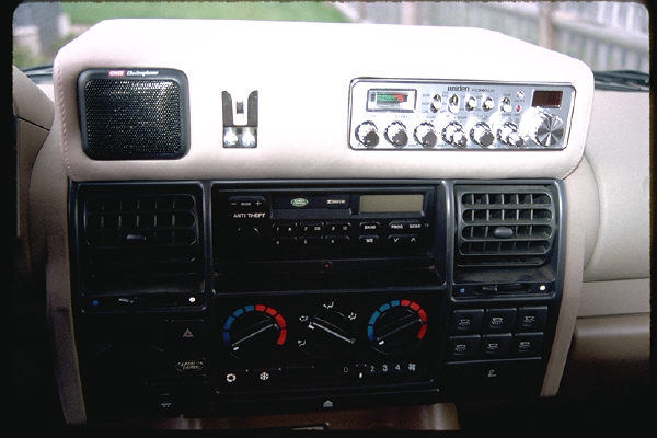
The final option that I am aware of that will maintain a factory look is to replace the coin tray with a part from a 1995 Range Rover Classic. This panel will allow the use of 6 switches and maintain a stock appearance. This is the approach I took (Illustration 1). Be aware that there are several switch types available for the panel, including a fog light switch, a dome light switch and several others that would likely be inappropriate to use as light switches. The fog light switch has an on/off indicator, while the dome light switch does not. Unfortunately, I was not aware of this until I had already ordered the switches.
All of the switch types mentioned (with the possible exception of the heated seat switches) above share a common wiring configuration. They all have 5 pins (labeled 1-5) which are setup as follows:
Pin 1: 12V DC
Pin 2: 12V DC from running lights
Pin 3: Not Used
Pin 4: Normally open contact switched to pin 1
Pin 5: Ground
If you do not care about on/off indicators or nighttime illumination, then only pins 1 and 4 need to be hooked up. However, if you want the switches to behave like all the other switches on your dashboard, you should hook up the other pins.
To my knowledge, the factory connector normally used to plug into these switches is not available except when buying a complete factory harness, so one must improvise. The solution is to use small (.110") female quick disconnects combined with some heat shrink tubing. This prevents the quick disconnects from contacting each other. If using the Range Rover 6 switch panel, it is also useful to connect pins 1, 2, and 5 from each switch to a common wire. All of the wires coming from the switches on this panel should be wired in a way that allows them to be removed if access behind the dash is needed. For this, I used a 12 pin Molex connector - 1 connector for pins 1, 1 for pins 2, 1 for pins 5 and 9 for pins 4. This obviously leaves me with the ability to hook up a total of 9 circuits on this one harness. For my project, 3 switches were used and I have an 8 conductor wire running from the passenger compartment to my custom fuse panel under the hood, so I have 5 circuits ready to go for future projects.
Pin 1 from each switch should be connected to a switched power feed so that the lights will only work with the key in the ignition and the vehicle running. Many people further suggest that they should only work with the high beam headlights on. In my case, I wanted use of the lights whether the headlights are on or not. Fuse number 18 is for the rear washer/wiper, side mirrors, and cruise control. This fuse gets power only when the ignition is on, so it serves my needs well. For tapping power off of a fuse, any of the electronics supply sources mentioned sell small metal clips that wrap around a fuse and provide a connection for a standard (.250") female quick disconnect.
Pin 2 from each switch should be connected to the parking light circuit. For my install, I tapped off of fuse number 2, which is the left hand parking light fuse, but this doesn't allow the dimmer switch to function for the switches. I plan to change this so that the switch lights will dim with the dimmer switch.
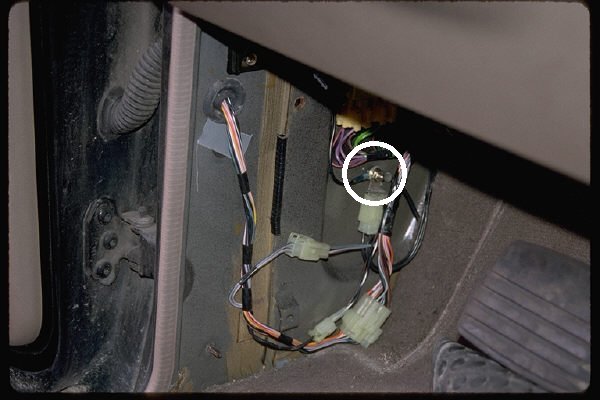
Pin 5 is the ground connection for the switch illumination. I connected this to an existing ground connection behind the driver's side kick panel (Illustration 2).
How to Route Wires
There are a couple of wire runs to be figured out for this particular project. The first has already been mentioned - running wires from the passenger compartment to the engine compartment. The second is getting wires from the roof rack into the engine compartment.
Routing the relay switch wires from the passenger compartment to the engine compartment is relatively simple. Under the hood on the left hand side, near the top of the firewall, there is a rubber plug covering a hole in the firewall. This plug can be replaced with a rubber grommet and you then have a place to route your wiring. In the passenger compartment, the hole comes through just above the fuse box - sticking a length of wire through from the engine compartment side will help you locate where it comes through. Once the wire is through, it is relatively easy to route it over to where the switches are located - it just takes some patience (and partial disassembly of the dashboard). In my case, I used marine grade 8 conductor 20 gauge wire that is bundled in a layer of insulation, so I had a relatively stiff piece of cable to work with and routing it to where I chose was a relatively simple task.
A better solution in the long run is to punch a large hole somewhere in the firewall and use a liquid tight strain relief so there is a moisture tight seal that also prevents the wires from chaffing. This also leaves you with room to run additional wires through the firewall at a later date (such as a CB antenna cable). Since there is somewhat limited space to work with, I suggest using a chassis punch to make the hole, as using a drill bit could cause very expensive problems (if it hits something it shouldn't).
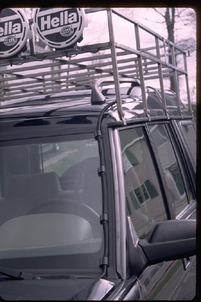
Figuring out the best way to route the wires from the roof rack into the engine bay turned out to be rather difficult. Most of the suggestions I received involved drilling holes in the roof or cutting slots in the weather stripping around the windshield to hold the wires in place. I really didn't like any of the solutions that were offered, especially considering that removal of the rack was a consideration, so I looked further. What I finally decided to do was to wrap the wire in plastic split loom tubing and run it along the left edge of the windshield, held in place with stick on quick release clips designed to hold the tubing (Illustration 3).
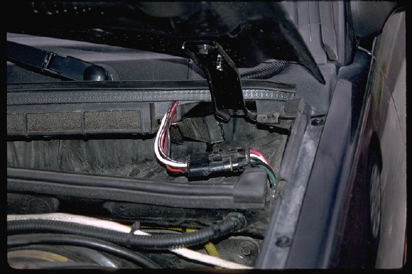
The next obstacle was to get the wire into the engine compartment. This was accomplished by opening the hood and pulling up the weather seal where the hood and windshield meet. Thanks to Land Rover's wonderful quality control, there was enough of a gap to run the wires through and then put the weather seal back. The wire is now under the hood, but in the channel where the windshield washer fluid lines run. At this point, I cut the wires and installed a Weather Pack connector (Illustration 4), which allows me to unplug the wiring and then remove all of the exposed wiring when the roof rack is removed. The channel has several unused holes covered with tape. Open up one of the holes, and the wires can run through into the engine compartment - the rest is easy - just route the wires to the fuse/relay panel, using cable ties to hold them in place. Enlarging the hole slightly and installing a liquid tight strain relief is an excellent alternative.
Under the Hood
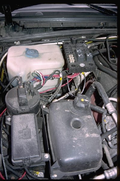
Instead of using the standard wiring harness that light manufacturers often include with lights, I wanted something that had wires long enough to reach the roof rack and gave me more flexibility where to mount the relay and fuse. The search for a solution turned out to be the most difficult part of the install. I initially settled on Littelfuse Powr-Bloks from Terminal Supply Company. This is a modular system that has various modules, such as relay blocks, fuse blocks, and numerous other options available. All of the various blocks connect together with very little work. I purchased enough blocks to give me 8 fuses, 8 relays, positive and negative power terminals, and mounting holes on each corner (Illustration 5). All of the electrical connections use crimp terminals, which then snap into the modular blocks.
The initial solution worked, but took a lot of space in the engine compartment, was tricky to mount, and started showing significant signs of corrosion after a few years under the hood. So I ended up redoing things and settled on the PS-1S Power Switch Kit from Centech Wiring and a waterproof inline fuse holder from Waytek, Inc. (search for part #46004). The PS-1S Power Switch Kit is a waterproof relay harness complete with wires that are long enough to reach just about anywhere you would want to mount lights on your Land Rover (except the rear). By using this harness, you can mount the relay to any number of convenient locations under the hood, and cut the wires to length. I decided to use the inline fuse holder so that the fuse can be easily replaced if blown, unlike the single use fuse that is included with the Power Switch Kit. The inline fuse should be connected as close to the battery as possible. I sold my Land Rover before updating this article, so I am unable to show how the wiring now looks but after approximately 4 years it was showing no signs of corrosion or any other issues.
Since I have the stock battery without side terminals, I connected a wire to the positive terminal of the fuse box in the engine compartment. The negative lead from the battery has a tap for ground connections just behind the battery. I added my ground connection to the existing grounds. When the battery is eventually replaced with an Optima battery with side terminals, I will move both connections directly to the battery.
Parts Sources and Manufacturers
Centech Wiring (http://www.centechwire.com) - they sell all sorts of specialized vehicle electronic solutions including pre-wired waterproof relay harnesses.
Waytek, Inc. (http://www.waytekwire.com) - they sell all sorts of wiring products.
Korit Sales, Inc. (http://www.korit.com), at 1-800-837-5674. Carry Greenlee Textron products and other tools.
West Marine (http://www.westmarine.com). They have retail stores all around the United States. I purchased all of my Anchor marine grade wire and crimp connectors here.
Terminal Supply Company (http://www.terminalsupplyco.com). When I called, they sent me a catalog (without price list). They will give you a quote for your order before placing it and accept Mastercard and Visa. I purchased miscellaneous crimp terminals, Littelfuse Powr-Bloks, Weather Pack connectors, a heat gun, crimping tools, etc. from them.
Chassis punches made by Greenlee Textron (http://www.greenlee.textron.com).
Liquid tight strain reliefs made by Altech Corporation (http://www.altechcorp.com).
You-Do-It Electronics. This is a local electronics supply store located in Needham, MA just off of Route 128. They carry test equipment, tools, wire, many types of terminals and electronics supplies. If you live in eastern Massachusetts, do not bother with Radio Shack - this place has much more and is worth the trip.
Land Rover Part Numbers
Range Rover 6 switch panel Part # AWR1159LNF
Range Rover auxiliary light switch Part # AMR3600
Land Rover Discovery 3 switch panel Part # AWR3330LNF
Land Rover Discovery fog light switch Part # AMR4138
Thanks.
Without the help of many people on the Coil Sprung Owners email list, this project would have taken me much longer to do. The people on the list offered all kinds of useful advice and made me feel much more comfortable tackling this project on my own.